System #473 (Aerius)

MartinLogan Audio Owners Forum

Help Support MartinLogan Audio Owners Forum:

This site may earn a commission from merchant affiliate links, including eBay, Amazon, and others.

user 2312

Well-known member
Joined
Jun 4, 2007
Messages
51
Reaction score
0
1. Member name: Luca Bolognesi

2. Location: Pisa, Italy

3. ML Model: Aerius (1992)

4. Year Purchased: 2011

5. Mods/Changes: I substituted original spikes with B.C.D. cones

6. Associate electronics:
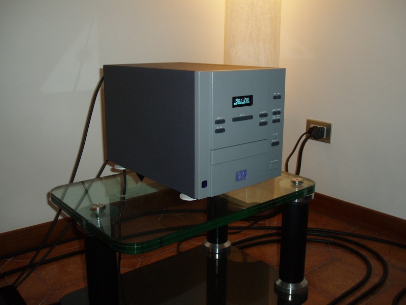
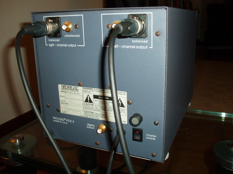
- CD player Madrigal Proceed PCD3
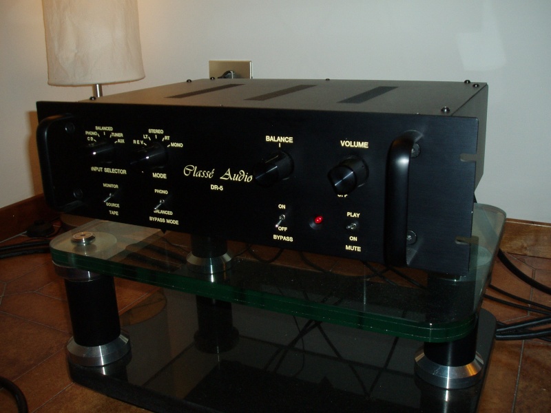
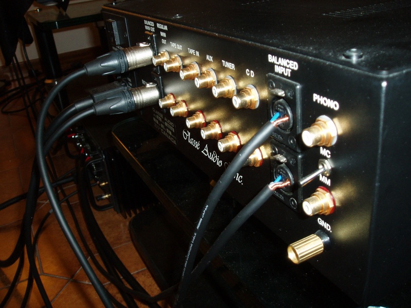
- Pre-amplifier Classe' Audio DR-5 (in/out balanced)
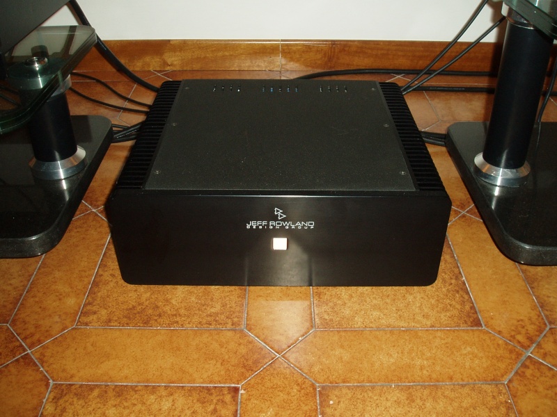
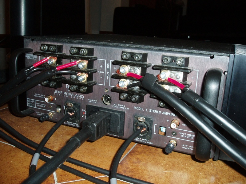
- Jeff Rowland Model One amplifier
- Roger Sanders balanced interconnects
- Straight Wire Maestro I speaker cables
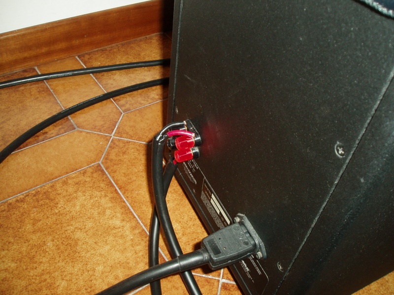
- Industrial neoprene-jacketed power cables (2.5 mmq) for wet environments
- B.C.D. supports

7. Comments: wonderful experience despite the bad acoustic response of the room. The JRDG Model One amplifier is perfect to drive the Aerius. The top of the panels are located at a distance of about 140 cm from the wall behind the loudspeakers. No apparent need for panels change despite their age.
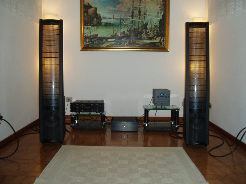
p9220011.jpg
 
Last edited:
Luca, welcome.....nice rig, don't let your poor acoustics of your room set you back. There are many solutions available !
 
Welcome, pretty cool system.
You would probably do well with some wideband bass traps in the corners.
 
Thank you for your messages! Unfortunately the room is too narrow for inserting a bookcase and I have to left the front wall for a video projector. But I hope to purchase a new house soon...
 
Last edited:
Welcome! I enjoyed my my pair of Aerius speakers for fifteen years. I bet they will respond nicely when you put them in your new home. There's a lot of info on this site you can access, to get the full measure of the speaker's capabilities.
 
Welcome Luca!

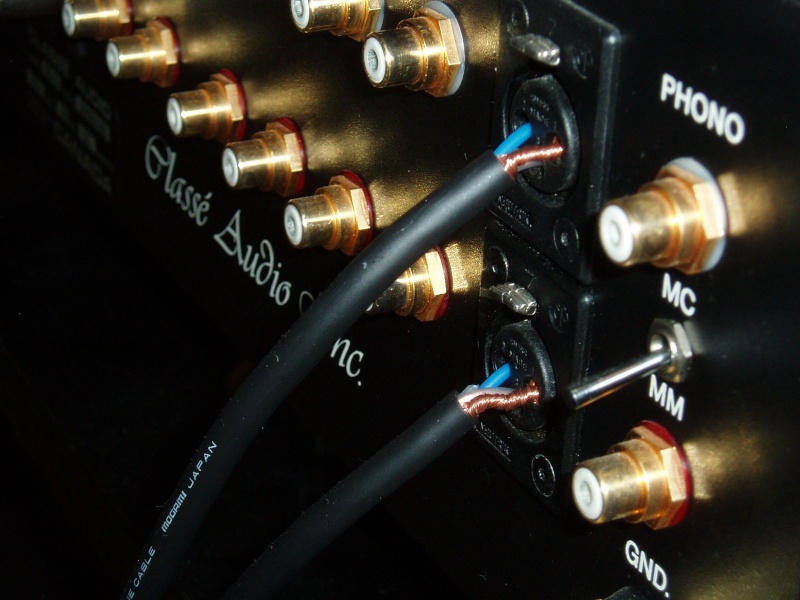
I'm surprised that you use interconnects without connectors. How do you ensure that the cables do not fall out?
 
Welcome Luca!

I'm surprised that you use interconnects without connectors. How do you ensure that the cables do not fall out?

I'll try to explain and I apologize for my approximated English...

I find that the sound is better without solder and still better without connectors. I use balanced interconnects.

The size of Mogami 2549 coated conductors almost fitted the female connectors of the electronics. I removed about 1 cm of the coating of the copper and I reversed the conductors like an umbrella during a storm. Now the cables simply entered the female holes and remained firmly enough in site. The shield can also fit well the third hole as its size depends on the degree of twisting.

Attaching the cables to the male connectors of the electronics without they fall out indeed appeared an impossible task at beginning... So I decided to utilize a device that has been created for this goal: the internal black plastic part (the one with the three holes) of the Neutrik NC3fXX connectors I owned. I removed all the metallic parts and I slightly increased the size of the holes by a small screwdriver. I removed about 2 cm (I suppose; just to permit to the naked connector to be slightly longer than the hole) of the coating of the copper and I inserted the conductors through the holes up to their exit on the other side (not too much, to avoid that each conductor touch the other). I repeated the same operation with the shield (not twisted), but it must be slightly pressed to avoid that it produce too much volume increase. I then attached the result to the male connector of the electronics. For easier handling, as I did, you can also rebuild the NC3fXX Neutrik connectors.

I hope that my explanation resulted clear enough...
 
Last edited:
Thanks for the explanation Luca. No need to apologize for your English; it's very good.
 
I introduced different interconnect and speaker cables. Work in progress...
 
Last edited:
Back
Top