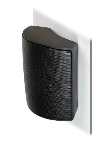
Hello everyone, looking for some help on my much loved SL3's that are not as happy as they once were.
The left hand channel lost output, and I have ventured to opening the back cover and looking at the PCB. I could see that the high voltage multipler had failed by the toasty components.
I isolated the speaker and removed the PCB in order to repair/replace the diodes/capacitors. I did not have any schematic but was able to identify the parts by looking at the early stages of the multiplier. I also replaced a few other capacitors with same make / model, where were not in the filter crossover but some other part of the circuit that looked like a signal detector switch on circuit. Anyway if it is possible to obtain a schematic that would help.
I was not able to verify the voltage as I did not have a suitable HV probe form my multimeter, but did remount the PCB and wire back up.
Powering up the circuit and playing some music showed the sound had returned, but there is a noticeable level.
Trying to be a little more objective, I ran a signal generator into my amplifier and then recorded the output on a portable sound recorded and external microphone. The speakers were measured individually in a smaller room with only the speaker under test in the room and the recording.
This was not a detailed anechoic level measurement, rather a more objective way of checking what my ears were telling me ! The amplifier was feed from a signal generator 30Hz-20kHz swept signal, 100Hz step at 0.5V RMS, then the amplifier output level was adjusted whilst observing the recorders input level. The measured power output was 25V RMS / 4 ohm. A Picoscope 5444D with MSO generated the signal, plus measured the output of the amplifier. Recordings were made on a Zoom 4Hn Pro with external Rode NT-2 microphone. The recording was 24bit/96kHz in BWF-compliant WAV format.
The recorded WAV file was then input in Audacity and the frequency response curves below were generated. As you can see, there is sizeable 20dB difference between the working and the low output speaker.
For the low output speaker you can also see the curve starts at same point but drops around 300Hz, I shoud have used a lowere frequncy step in mysetup, but you can see the crossover and that the bass was the same. So this shows the HF panel. However, I do not necessailye think the panel is the issue, but more likely the PCB could still have issues. I will order a HV probe kit so I can measure the HT.
If anyone has an SL3 schematic I would be most grateful.
Many thanks, Mark from very wet England !


